Monday, 30 June 2014

Scratch Pine Toronado: Pickguard Template

While I wait patiently for my router bits and cavity templates from Stewmac, I though I'd have a go at transferring the pickguard from the pdf design to a thin MDF sheet ready for shaping the pickguard material. It was pretty straightforward; involving pretty much the same procedure as with the body template.

First I cut out the pdf on to A4 paper and stuck it together with sticky tape. Using the neck template and the bridge positioning distances calculated from the Stewmac fret position calculator, I oriented this paper template between the neck cutout and the bridge. This gave me the first hurdle to overcome - the hard-tail bridge that I've selected for this build sits further back than the stock Toronado bridge referenced in the design. This meant that the pickguard design needed some freehand alteration to move the bridge surround lower, and to shift the side edges out and down to meet this new surround placement.

With the alteration made, the second step was to glue the paper template onto the 4mm MDF and cut roughly around it with the band-saw. This done, the bench sander allowed me to smooth off the majority of the convex and concave curves. The tight corners around the bridge and in the neck cavity proved the most fiddly, requiring a fine curved file to slowly remove material until the desired shape was reached.

Finally, the job was done and the pickguard template looks pretty good:


I'll have to wait for my templates from Stewmac before I can add the pickup routes in the pickguard. This will provide it's own set of challenges, but I'm ready and raring to go!

Sunday, 29 June 2014

Stone Roses Tribute: 9th Colour Layer (Second Coming)

Well, the Pollocking is coming along (again) and hopefully I'm creating something that will come close to what we had before. The 9th colour layer (black) is on and I'm ready to start the cycle again. Here's what she looks like:


I think it's looking pretty good, but only time will tell. It's a lot more nerve-wracking this time around given that I had something special the first time! By way of comparison, here's what she looked like at this stage last time:


This time, I put more white on in layer 8, which has masked off quite a bit of the more brilliant colour layers. These will come back with the next colour cycle.

Monday, 23 June 2014

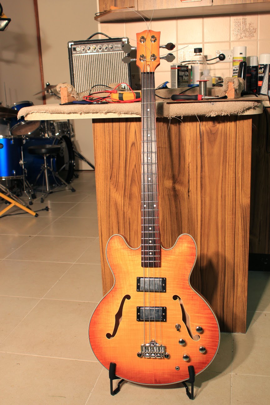
335 Semi-hollow Bass: She's a Stunner!

The 335 bass is now officially complete. The headstock decal went on this morning, and she finally got a fret level and re-dress. Nothing short of amazing now to play. What started out as an ESB-4 kit from Pitbull Guitars is now a rockin' instrument. Now all I have to do is learn a few more bass riffs!


I am so happy with how this kit came out, and oh-so happy with how she feels to play. So much so,  that I am seriously considering building another one. I can see this beauty in trans-black hanging on my wall. Sounds good doesn't it??

Postscript 8th July 2014:
I've just been informed by the good folks at Pitbull guitars that this little beastie has taken out Pitbull Guitar of the Month for July. Woohoo! Thanks guys!

Sunday, 22 June 2014

Scratch Pine Body: MDF Templates

Today I roughed out some MDF templates that will be used to shape the Toronado body and route out the pickup and control cavities. I started by printing the pdf template over multiple A4 pages using Adobe PDF Reader and sticking them together with tape. This was then cut out and pasted on to 12mm MDF using spray on adhesive. This allowed me to roughly cut around the guitar shape using my el-cheapo bandsaw.


After the bandsaw, I used the bench sander to finish off the convex curves on the sides of the body template. I'm very happy with the resulting edges of the template - nice clean lines with which to route the final pine body shape.


For the tight concave curves, the banch sander was not an option. Instead, I used two sizes of Josco Brumby flap wheels which, when attached to the chuck of my even more el-cheapo drill press, allowed me to make quick work of them. This completed the smoothing of the template sides.


Lastly, the pickup and switch cavities were added to the template. This was achieved using the drill press to create the rounded corners, the jigsaw to join them up, and the flap wheels to clean and smooth the sides. I opted for creating a "swimming pool" type cavity for the pickups this time around. I'll be relying on the pickguard to cover the cavity similar to a strat.  As my experience with the router is very limited (ie none at all), the easier I make the routing on myself the better.


With the body template created, the next template required (and to be honest the most important), was the neck pocket. To rough this out, I first consulted the (printed) PDF template to get a feel for the overall neck cavity required. The neck was then placed on top of this PDF template to determine how the neck heel compared with the template, and how the neck would be oriented on top of the neck base.


This was traced to get the rough shape of the very heel of the neck, and the resulting cavity was roughed out using the drill press and jig saw. Once shaped, the neck was fitted into the cavity and refined using successive applications of the bastard file until a tight fit was obtained.


I'm still not sure if what I am doing is correct, or whether it will end in utter disaster; especially where the neck pocket is concerned. I guess I just need to keep on going and see how it turns out. I'm a bit skeptical that in my hands the bastard file has produced a neck pocket template with sides that are sufficiently straight, clean and even. It's a tight fit and all, but now I'm worried that the neck isn't going to be straight with respect to the rest of the guitar. I don't know how to alleviate this worry other than to forge ahead and see what happens...

Saturday, 21 June 2014

Scratch Pine Body: Fender Toronado!

Shopping for a decent body shape for this pine scratch build, I happened upon the Google docs Guitar Plans Collection. Here you'll find plans for every guitar body shape under the sun! Since the neck I am going to use is a cheap Chinese Telecaster neck, a Fender shape was always on the cards. Rather than make yet another Telecaster, however, I opted for a body with a similar size and neck pocket but with more of an alt shoe-gazer feel. Enter the Fender Toronado!


It's kinda Jazzmaster'ish, with its large top horn and small lower nub, and I really like that look. It's a shape that I personally associated with "Vintage" looking guitars, even though the Tele, amongst others, is a much older design. Anyway, the plans from Google docs include the body shape, pickguard and neck pocket so I should be able to use it for all my routing and cutting requirements.

After 24 hours, the clamps came off the body today and it was on to the 40 grit sandpaper to get the front and back of the body levelled up - basically what professional luthiers, or even sane individuals, might do with a thicknesser. I've got one of those fucking annoying orbital sanders with the little bar clamps either end. Do you think the paper would stay fixed in there for more than a minute at a time?? Nup!


Consequently it's taking an age to get the body blank level(ish) but, with dogged determination, I'm persevering. $400 for a cheap thicknesser? Believe me, it's looking cheaper by the minute ;) ! Despite my little whinge, the results are very promising! The blank is looking nice (and piney) and is just wide enough to accomodate the Tornado body shape.

I have printed out the plans (downloaded as pdf) and am in the process of sticking them to 12mm MDF so that I can cut out templates for routing. I'll let you know more about how that goes in the next installment. Stay tuned!

Friday, 20 June 2014

Scratch Pine Body: Making a Cheap Blank

With a few kits under my belt, I am really feeling the call of the scratch build. While making my own neck still seems like a very tall ask, shaping and routing a body from scratch isn't beyond the borders of possibility. How hard could it be? Well, I aim to find out!

Now tone wood is generally expensive, and a pre-made body bank can set you back anywhere from $100 and up. Even the local lumber yard wants nearly $100 for the timber required to create a really nice 3-piece blank in mahogany, ash or Tasmanian blackwood. While Maple was the cheapest I was quoted, coming in at around $60 for the equivalent of a body blank, thats still a lot of money to go throwing away on a failed attempt.

And so, enter the pine body - a cheap way to earn my luthier chops without breaking the bank. Bunnings stock a 1.2m length of finished pine 45mm x 90mm that's just perfect for making 4-piece 45mm deep bodies. Just two of these 1.2m lengths, at $9 a pop, is all you need for a standard body blank - that less than $20 people! Much more within my comfort zone for learning this black art.

And so off to Bunnings I tromped and got me some pine - enough for two bodies. In no time each piece was halved into 600mm lengths and ready to be glued together with Titebond - the king of wood glues.


I slathered each side of each piece with Titebond - enough to drown a rather large horse - and then got the pieces all clamped together with 46mm clamps.


After I was engulfed (yet not consumed!) by the ensuing wave of escaping Titebond, I did a little cleanup and now must wait a couple of days for the glue to dry. Unfortunately I only have 4 clamps, so the second body will have to wait.

Once the glue dries, the next step will be squaring off the ends with my new (el-cheapo) bandsaw, and flattening off the top and bottom with 40 then 80 grit sandpaper. I'm really excited to see how this turns out, although I'm well aware that this is the *easy* part of the process. after this I'm going to have to think seriously about where this thing is headed!

A big thanks to Warren Gaull from 4D Guitars for suggesting the pine scratchy to me. You've stared me on the long road to luthier awesomeness Wokka!

Wednesday, 18 June 2014

335 Semi-hollow Bass: Sound Demo

OK, so for those of you interested in how this semi-hollow beast sounds, I have done a quick sound demo. Please excuse the crap playing. The bass is being played through a Fender Deluxe 112 guitar amplifier with no additional pedals or effects other than a bit of reverb provided by the amp itself.


I'm certainly no bass player, but I gotta say, I love the way this baby sounds. Deep and booming, yet very clear and crisp. It looks so awesome, and sounds so good, I'm sorely tempted to make myself another one! I never knew how much fun playing the bass could be.

I've still got the headstock decal to go before I call this one finished, so hopefully that will all be done and dusted by the weekend!

Tuesday, 17 June 2014

335 Semi-hollow Bass: All wired up

OK the wiring harness went in without a hitch today. It took all of 20 minutes to get the pots, output jack and 3-way switch into the body and the nuts tightened down. It's a new record! Third time building a semi-hollow has sure honed my skills.


Anyway she's looking really nice now and she sounds amazing through my solid-state Fender guitar amp. All that is left to do on this baby now is a fret level and re-crown, create a suitably awesome custom truss-rod cover, and stick my headstock decal on.

Saturday, 14 June 2014

335 Semi-hollow Bass: 50s Vintage Wiring - Tweaked!

In the process of creating my wiring harness for the 335 bass, I have re-examined how to go about laying out the wiring harness for a semi-hollow build so that it is both simple, and will survive the installation process. For my other semi-hollow builds (the 12 String 335 and the Les Paul Florentine) I used the following circuit. It's a Gibson 50s Vintage wiring scheme, with the independent volume mod added for good measure.


While this orientation is perfect for wiring those big arse oil-caps into small Les Paul control cavities, when you are talking about mounting in a semi-hollow body those capacitors wired "inline" between the volume and tone pots are devilishly hard to secure. You end up attaching wires to one or both ends of the capacitor legs, and then lashing this to another of the joining wires for stability. All in all, it's a hack at best!

Instead, there is actually no reason why the capacitors couldn't be mounted to the back of the tone pots instead. You see this orientation very often in Fender wiring schemes, and in other single volume / single tone configurations. It's actually a very convenient way of mounting the tone capacitors, especially for semi-hollows! Taking the wiring diagram above, it's a simple matter of shifting the capacitor from before the variable resistance in the tone circuit to "after" it instead. The result is electrically equivalent and much easier to secure and install.


In this configuration we need only piggyback the tone caps to the back of the tone pots. No additional wires need be soldered to the capacitor legs, and no lashing is required to secure the capacitor in place. It's so simple and elegant, why the hell didn't I think of it before??

Anyway, the sucker is wired up. With the volume pots at the top and tones at the bottom the wiring harness is surprisingly neat.

Friday, 13 June 2014

335 Semi-hollow Bass: Strings!

The clamps came off the set-neck this afternoon and the strings went on for an acoustic test of the semi-hollow 335 bass. While the action is a little high, I'm really loving how the finish has come out. She looks so awesome - if I do say so myself ;).


Suffice to say, there was more than a little bit of acoustic dum-dum-dumming here in the man-cave once she was all tuned up. I so wish I could play bass! Now it's just the electronics to go. Did I say *just* ? I'm sticking with the original kit-supplied pots for this one (not the larger CTS pots or their ilk) so I'm hoping it won't be as much of a struggle getting the wiring harness into the cavity. First though, I need a wiring harness!!

Thursday, 12 June 2014

335 Semi-hollow Bass: The Neck is Set

With the clear coats finally in an acceptable state, it was time to glue the set neck onto the 335 bass. Before I could do that, I needed to drill a hole for the bridge ground wire from the front bridge post out into the cavity. This time I remembered to use a metal ruler to protect the finish from the side of the drill bit.


All was completed successfully, and the ground wire was installed by baring some of the wire, turning this downwards into the post hole and then inserting the the post into the hole. A multimeter attached to the bridge post and the end of the ground wire indicates very quickly whether the bare wire is making contact.


With the grounded bridge post installed, the other bridge posts could be pushed in and the bridge mounted to allow the outside strings to be aligned down the neck. With this looking good, it was time to get out the Titebond and slather it into the cavity and onto the neck heel. The clamp went back on (tight!) and now it is left to dry for a couple of days.


I am a little concerned that the neck could come over more towards the E string at the tuner end. The string is sitting a little too far into the fretboard down at the pickup end of the fretboard for my liking. But try as I might, I could not get the neck to twist horizontally any further. It's definitely playable as-is, and this certainly wasn't a visible issue during the mock build,so we'll have to wait and see what it looks like when the clamp comes off.

Wednesday, 11 June 2014

Burley 335: Unboxing

A spanking new kit dropped on my doorstep this morning courtesy of DIY Guitars Australia. It's the new ATH-26, a semi-hollow 335 style kit, topped with a burled, birds-eye maple veneer and powered by two P90s. I had high hopes for how this baby would look and I wasn't disappointed! The top veneer really looks amazing. There will be no dye needed for the top of this baby - some clear coats is all it will take to make her look spectacular.


The grain has been filled in a couple of places (most notably inside the burls) at the factory, and there are a few places where some quite open grain still exists in the veneer. I'll have to find some kind of clear grain filler for these. The rest of the grain on the back and sides looks great, without any visible glue spots or other blemishes. The neck also looks good - with some nice maple grain down it's  length and on the headstock.


The fretboard looks good with no machine marks or scratches. There is a small issue with the width of the neck at the heel - it is a very tight fit into the neck pocket (this is a set-neck kit). In fact it is so tight that I can't get the neck all the way down into the pocket. Looks like I'll have to sand a little off each side of the neck heel before it will reach the bottom. No sweat - at least this will guarantee a tight fit and that's perfect for a set-neck build.


Despite this small issue, all in all I'm very, very happy with the kit and I think it looks awesome - I'm really looking forward to this build!


First thing will be the mock build to make sure everything fits (including sanding the neck heel) and then I'll be able to start the finishing process. I have a real soft-spot for hollow and semi-hollow guitars, especially the 335 body shape. Whist this baby will be the 4th semi-hollow kit I have attempted, it's the very first with P90s. I really can't wait to hear their vintage growl coming from a 335. Total awesomeness!

Sunday, 8 June 2014

Surf Monster Telecaster: Seafoam v2.0

The first coat of seafoam green went on to the Surf Monster Telecaster v3.0 today. The primer levelled out nicely with 800 grit sandpaper and the first coat of seafoam green (in truth Ironlak 'Linz Iceberg' from Ozgraff) went on without a hitch. Looking at it now I'm really glad I went back to my original vision for this Tele.


This time around the Ironlak didn't splutter and drip like last time and I was able to lay down a nice thin, even coat. The secret was a finer spray nozzle - also courtesy of Ozgraff. The original supplied nozzle on all the Ironlak cans was ridiculously high volume, and I believe that this led to the coats being way too thick the first time around. I guess a high volume jet is just what the hoodies down by the train tracks need to realise their singular works of art, but it's not so good for creating nice even guitar colour (at least in my hands).

I've just about convinced myself that the the cracks in my first clear attempt was due to the paint underneath being way too thick (and therefore not dry or hard enough). I could be wrong (I'm certainly no expert) but this time around everything feels more normal; more like previous builds. I guess we'll see how it finishes up, but I'm quietly confident everything will turn out well. Famous last words!!

Saturday, 7 June 2014

Understanding the 5-way Switch

Whether it's controlling your Stratocaster or your sleek Ibanez shredder, the 5-way switch is the most common switch choice for 3-pickup guitars out there today. And yet, as popular as it is, the unassuming 5-way is one of the least understood switch types used in guitar wiring.

Whether you're thinking of wiring your new guitar build, modding your existing axe, or even creating some mind-blowing wirings for your 2-pickup guitar, an understanding of the 5-way switch and how it operates is central to getting your wiring correct.

In general there are 3 flavours of 5-way switch out there. These are the standard Fender switch - having 8 pins, 4 to a side - and 2 kinds of import switch having either 7 or 8 pins in a row across the bottom.


No matter which configuration you have, the operation of the switch is identical in all cases. You need only identify the specific pin configuration provided by your switch to apply it to your own particular wiring design.

The most important thing to know about the 5-way is that, internally, it operates as a 2-pole / 3-way switch. This means that internally the switch is made up of 2 lots of 3-way switches as shown below left. Each 3 way switch directs one of 3 input signals (or a combination of them) 1, 2, 3 to the output 0.


In terms of the Fender standard 5-way, each set of 4 pins on either side represents a single 3-way pole.  For the 8-Pin Import switches, the leftmost 4 pins correspond to one pole, and the rightmost 4  pins correspond to the second pole. The 7-pin configuration is identical to the 8-pin, except for the fact that both poles share the same central output (0) pin.

With each pole operating independently, the following connections are made in the 5 switch positions:

Switch PositionBlue (0) Connected toOrange (0) Connected to
1Blue (1)Orange (1)
2Blue (1) and (2)Orange (1) and (2)
3Blue (2)Orange (2)
4Blue (2) and (3)Orange (2) and (3)
5Blue (3)Orange (3)

It's operation is pretty straightforward once you know the pin assignments! For a standard H-S-H set-up, only one pole of the switch is required to give a simple 1: N, 2:N+S, 3:S, 4:S+B, 5:B switching configuration since all these combinations map directly to a single column in the table above.


The second pole comes into it's own when coil tapping can be employed to split humbuckers into single coils. For example in the wiring diagram given below.