As a guitar builder with a degree in Computer Engineering, I really should have been making use of my professional skills in the pursuit of guitar hardware a lot earlier. But now with the advent of the Arduino and a little spare time for me to get to know it, the possibilities have opened up for the quick prototyping and development of small guitar-related projects!
As a introduction for myself, I thought about building a simple footswitch pedal - one with more inputs (and hopefully more outputs) than the standard offering. It's a pretty simple application of the Arduino, driving a few relays (one per input jack and one per output jack) a few indicator LEDs and an LCD screen to show the current switch state. With two momentary footswitches (instead of the normal 1) I will be able to independently switch between multiple inputs and multiple outputs.
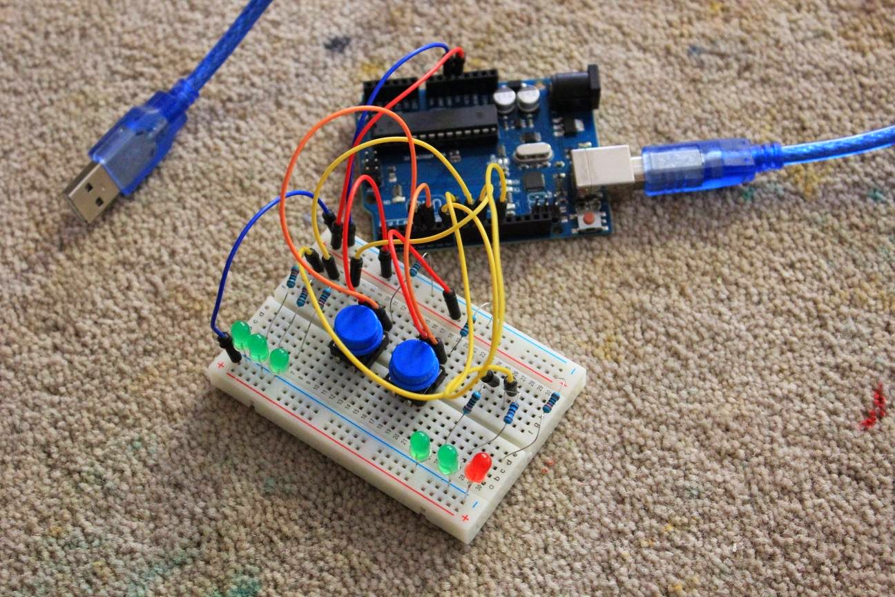
I received an Arduino Uno starter kit the other day and proceeded to construct myself a working prototype. The first step was to read the state of the momentary footswitches, detect a switch press event, and then update the internal state as indicated by a bunch of LEDS - one per input and one per output. To begin with I implemented a 3-input 2-output setup.
This was very easy to achieve given the example circuits and code floating around the interweb. Next job was to get the LCD screen working. I bought an SPI (serial protocol) enabled 16 character x 2 LCD screen and proceeded to wire it up with help from ArduinoInfo. With only a serial data TX and RX to connect up (2 wires!) these SPI LCDs are awesome - very quick and easy to get working.


A little code to write strings to the screen and hey presto - the LCD screen is initialising and changing it's output based on the current selection of input and output. Pretty impressive for a first try, and to be honest it was simple-as! I'm just waiting on some optically isolated relay boards to finish all the internals off, and then I can do a real test with real audio input and output. I'm hoping that the relays won't introduce any noise into the audio path.
Using an Arduino Nano, all this should fit quite neatly into a stompbox enclosure just a bit larger than normal. I already tried a 1590BB enclosure but unfortunately it's a little shallow to take all the inputs and outputs as well as the PCBs for the Arduino and relays. Looks like I'll be off to Jaycar to get a more appropriate enclosure..
As a introduction for myself, I thought about building a simple footswitch pedal - one with more inputs (and hopefully more outputs) than the standard offering. It's a pretty simple application of the Arduino, driving a few relays (one per input jack and one per output jack) a few indicator LEDs and an LCD screen to show the current switch state. With two momentary footswitches (instead of the normal 1) I will be able to independently switch between multiple inputs and multiple outputs.
I received an Arduino Uno starter kit the other day and proceeded to construct myself a working prototype. The first step was to read the state of the momentary footswitches, detect a switch press event, and then update the internal state as indicated by a bunch of LEDS - one per input and one per output. To begin with I implemented a 3-input 2-output setup.
This was very easy to achieve given the example circuits and code floating around the interweb. Next job was to get the LCD screen working. I bought an SPI (serial protocol) enabled 16 character x 2 LCD screen and proceeded to wire it up with help from ArduinoInfo. With only a serial data TX and RX to connect up (2 wires!) these SPI LCDs are awesome - very quick and easy to get working.
A little code to write strings to the screen and hey presto - the LCD screen is initialising and changing it's output based on the current selection of input and output. Pretty impressive for a first try, and to be honest it was simple-as! I'm just waiting on some optically isolated relay boards to finish all the internals off, and then I can do a real test with real audio input and output. I'm hoping that the relays won't introduce any noise into the audio path.
Using an Arduino Nano, all this should fit quite neatly into a stompbox enclosure just a bit larger than normal. I already tried a 1590BB enclosure but unfortunately it's a little shallow to take all the inputs and outputs as well as the PCBs for the Arduino and relays. Looks like I'll be off to Jaycar to get a more appropriate enclosure..
No comments:
Post a Comment